


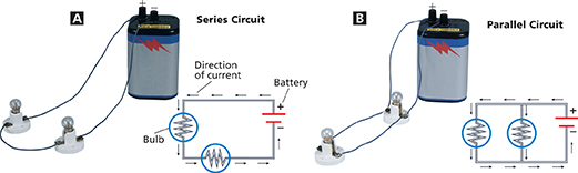
Figure 12 Circuits can be represented with circuit diagrams. Symbols correspond to each element. A A series circuit has one path that each charge can follow. B A parallel circuit has more than one path each charge can follow.
Interpreting Diagrams Which symbol represents a light bulb?
 dd
ddFigure 12 shows two circuit diagrams. The + and on the battery symbol indicate the positive and negative terminals. Arrows show the direction of current, from positive to negative. Recall that the direction of current is defined as the direction in which positive charges would flow. Electrons in a wire flow in the opposite direction.

How is the direction of current defined?
Series Circuits
In a series circuit, charge has only one path through which it can flow. Look at the series circuit in Figure 12A. If one light bulb burns out in a series circuit, it becomes an open circuit.  If one element stops functioning in a series circuit, none of the elements can operate. The bulbs in a circuit are a source of resistance. Adding bulbs to a series circuit increases the resistance. As a result, the current decreases, and each bulb shines less brightly.
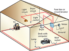
Figure 13 Most circuits in a house are parallel. This way, even if one device stops working, the others will still work.
Parallel Circuits
Imagine what would happen if circuits in your home were wired in series. If a light bulb burned out, the television would turn off. To avoid this problem, circuits in the home are mostly wired with two or more paths through which charges can flow. If one bulb in Figure 12B burns out, charge still flows along the other path, and the other bulb stays lit.  If one element stops functioning in a parallel circuit, the rest of the elements still can operate.
Figure 13 shows a network of circuits connecting electrical devices in a home. These circuits are wired in parallel so they can operate independently.